
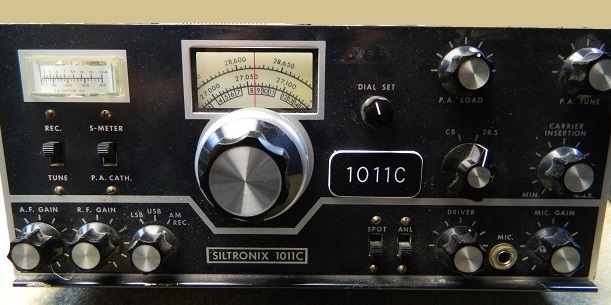
Siltronix 1011C
or lets drift again like we did last Summer.
By KC5RT
If you are new to HAM radio, you may not know the history of the Siltronix 1011 radio. The first of these models was build by SWAN. If you look inside the rig and compare it to other SWANs of that time like the 260/270 series you will see just how similar they were. SWAN ran into trouble with the HAM Radio community because the 1011 was easily modified to transmit on 11 meters (CB band) and was marketed to the CBer. It was and still is illegal to transmit using the 1011 on the CB bands. The Siltronix company was a spin-off of SWAN and they continued to build the 1011 in various models. The most popular model was the 1011D. The 1011D and the 1011C are nearly identical. The D model used a solid state balanced modulator where most of the C models still used a tube for this function.
The Siltronix 1011 radio uses a simple single conversion system. That means there is only on step from RF to IF in the receiver and from IF to RF for the transmitter. The VFO was this radios weak point. The VFO had to operate at a high frequency (22 to 23MHz) and in two or more ranges to provide the Local Oscillator function. The combination of high frequency operation and mechanical LC band switching made this design hard to stabilize. The rigs drifted like crazy and even after warm up you had to keep you fingers on the dial. The VFO operated on a -12 volt Zener diode regulator and the band select switch became part of the frequency determining LC network. A dirty band switch would cause large jumps in frequency.
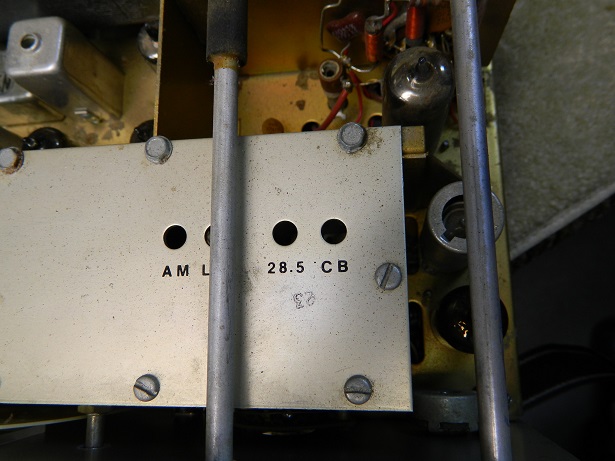
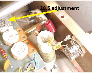
Since these radios were designed and built before HAMs had voice privileges below 28.5MHz it is necessary to adjust the 28.5 trimmer cap to slide the VFO down 200KHz for use on today's popular 28.300 to 28.500 HAM band. In most VFOs this can be done by simply adjusting the air variable trimmer cap marked 28.5.
When doing this adjustment set the dial set knob to 12 O'clock ,set the VFO dial to read 28.500.
Use a non metallic screw driver and go slowly as it only takes a small tweak to move the VFO to 28.300.
You will need a frequency counter, or the FD1011 display to set the VFO.
A local receiver tuned to 22.800MHz can also be used to zero beat the VFO.
Of course once you move the VFO the analog frequency dial will still show 28.500 when the rig is actually on 28.300. If you have the matching FD1011 frequency display you will see the new frequency range and all will be right with the world.
Well maybe if you can stand to hear the complaints from others about the drift.
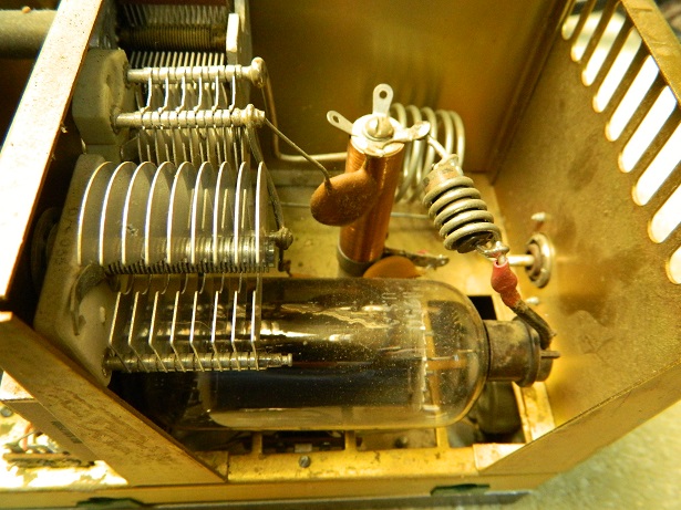
In this photo you can see the 8950 single tube 100 watt amplifier. Getting the tube in and out of the cage can be a challenge. Remove the plate cap first.
Another little issue with the 1011 is its final amplifier tube the 8950.
It's a great tube, but it is getting hard to find and with anything rare more and more expensive. A good 8950 will cost you 100 dollars on today's surplus market. Low transmit power is almost always a sign of a weak 8950. Keep in mind these rigs were run in AM mode on the CB band and that a high duty cycle can really take it's toll on sweep tubes.
There is a modification that can be made to replace the 8950 with another type of sweep tube such as the 6LB6. The 6LB6 is a pin for pin plug in and is more readily available and only about 30 dollars. You just need to re wire the filaments in the whole radio to provide 6.3v to the 6LB6 instead of 12v for the 8950. The Siltronix 1011 Yahoo group, https://groups.yahoo.com/neo/groups/Siltronix1011Bunch/ has a complete instructional file on this modification.
If you decide to change the tube from an 8950 to a 6LB6 be sure to get a tube that will fit. Many sweep tubes came in different heights depending on manufacturer.
If you have just picked up one of these radios and want to get it going on the 10 meter band here are some things to do first. Take the case top and bottom off of your rig. Start checking the carbon comp resistors. I find at least a half dozen bad resistors on these old rigs everytime. One clue is if the carrier balance is no longer centered to achieve balance. The most common resistors to change value are those 100K and above. Also check the 10watt power resistors and the electrolytic capacitors on the rectifier board. There are also several smaller electrolytics under the chassis that tend to dry up. The small white plastic types are always bad. All of these caps are prone to failure from age alone. A lot of these radios come to me with blown rectifier diodes, if your fuse blows at power up check these diodes on the rectifier board first and replace all of them with 1N4007s even if only one is bad..
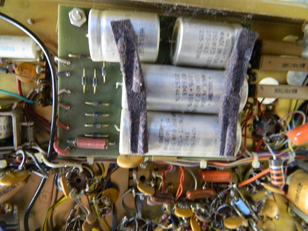
The rectifier and filter board can be swung up and way so that the components can be changed without removing wires. However, it's a good idea to make a drawing of the wire colors and terminal placement before removing the board.
On occasion a wire or two will fly off of a terminal and you will spend many minutes trying to find the correct terminal. This is experience speaking.
Not all radios have the same colored wires in them.
Once I have done the no power inspection and defective or out of spec part replacement, I turn on the radio and see what works. Of course, I reinstall the top and bottom of the case just to be safe.
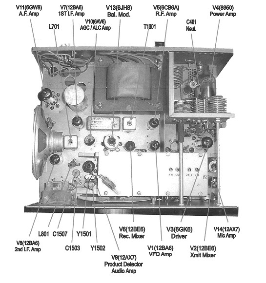
At the left is a scanned page from the Siltronix Maintenance Manual.
This shows the location of the major components. Note that the balanced modulator is a 6JH8 tube. Many if not most 1011Cs that I have seen have the harder to obtain 7360 tubes.
If you suspect the 7360 to be bad and can't find a replacement, it is easy to change the tube to a 6JH8 by re-wiring the socket. Every pin except the filaments will need to be moved.
You'll need to rewire the 7360 socket as follows in order to use the 6JH8 in place of the 7360:
7360 -------6JH8
-------------------------
1 --cathode-- 7
2 --sup grid-- 3
3 --con grid-- 6
4 --filament-- 4
5 --filament-- 5
6 --plate #1-- 8
7 --plate #2-- 9
8 --deflector1-- 2
9-- deflector2-- 1
No other changes are needed.
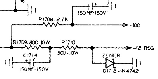
The VFO is powered by this -12 volt source. Often the Zener diodes are open and this causes excessive drift if not out right VFO transistor failures. Always check this diode and replace it if bad. A shorted diode results in no VFO operation and smoke from R1710. If R1710 was open in your initial checks suspect the Zener is shorted.
The 1N4742 diode is a 12 volt 1 watt Zener. It can still be purchased from Mouser as 78-1N4742A for about 0.10 each.
This circuit provides about 5% regulation.
I have also used an LM7912 3 terminal regular in place of the Zener with good results. The VFO drift was improved too as a bonus.
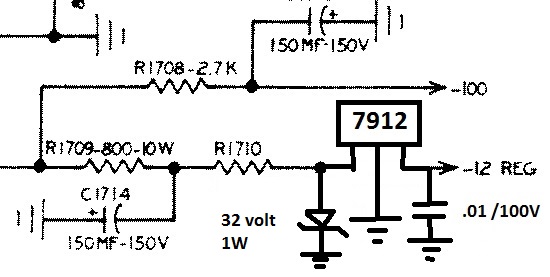
In the diagram to the left you can see the simple LM7912 circuit. This circuit provides better regulation over temperature and thus reduces some of the VFO drift caused by voltage variations.
The 32 volt Zener ensures that the 7912 never sees a voltage above its max rating of 37 volts.
The Mouser part number for the 32 volt Zener is 78-BZX85B32-TR. Also about a $0.10 price.
The 7912 will get warm but doesn't need a heat sink.
A few more tricks to reduce the VFO drift.
Put a 12 volt computer fan on the final amplifier cage and power it from the +12 volt supply diode. These small fans are available for a few dollars. You want the fan to suck the heat out of the final cage but not into the radio. Take the 12 volts from the plus terminal of C1702. This is a 100 MFD / 35 volt capacitor. Connect the red wire form the fan here. Connect the black wire to any ground or chassis terminal.
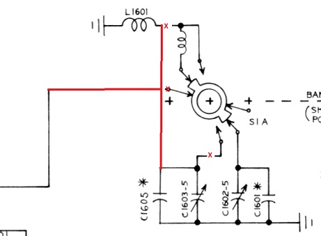
Another modification to the VFO but one that limits the use of the radio to 10 meters is to remove some wiring from the band switch and directly connect the 10 meter LC components to the VFO circuitry. I find this to be a significant improvement, but again you will not be able to listen to the CB band. I'm sure you wouldn't think on transmitting there anyway so really it isn't a big loss of functionality.
Leave the band switch intact but remove the wiring from the switch and run a # 14 awg wire from the L1601 coil to the trimmer board. Run the wire that comes from the VFO board to the wiper of the switch directly to this same point on the ceramic coil.
You can leave the small coil on the switch, as long as you remove the wires that connect to C1605 and L1601. This way you can always easily go back to original circuit if need be.
Transmit Audio
I get requests to fix the transmit audio on these rigs quite often. The fix usually requires an alignment of the carrier oscillators. The crystal trim caps are just too tempting not to be turned to see what happens. Keep in mind that many of these old rigs saw years of CB service and golden screw drivers are plentiful.
To properly align the carriers you need an audio signal generator, an RF power meter, and the Maintenance Manual. You can however, adjust the USB and LSB carriers if you have a local receiver and some head phones. Tune in the signal from the 1011 on a local receiver and listen to the audio. Adjust the trim caps of the appropriate carrier oscillator crystal using a non metallic screw driver until you get an audio response you like. I don't recommend this method but if you don't have the test equipment it is worth a try. Always mark the caps orientation on the chassis before starting, Never use a carbon pencil to mark the caps or the chassis. A felt tip marker is best. The carbon can get into the caps. This way you can always get back to where you were. RF output power may suffer if the carrier isn't properly adjusted.
Once you have the carrier oscillators adjusted check the audio response from the microphone amplifier. There is only one change that I can recommend here, and that is to increase the value of C1406 from 100 PFD to .001MFD. This will cut out much of the high frequencies and give a lower tone to your audio. Try it and if you don't like it switch back to the 100PFD.